*This article was published in Vol. 51 No. 7 of Cycle Canada digital magazine.
Click here to read the part one.
As we noted in our previous column, a hydraulic braking system works by converting the mechanical force we exert into hydraulic pressure, which is then converted back into mechanical force. We will now look further into the key components of such a system.
The master cylinder
The mechanism of this chain begins with the master cylinder, a small piston pump controlled by the brake lever. The initial transformation takes place here, where mechanical force is converted to hydraulic pressure. Without getting too deep into the physics of the matter, you should know that the hydraulic pressure produced is in inverse proportion to the area of the master cylinder piston. In other words, and contrary to popular belief, the smaller the piston, the greater the hydraulic pressure produced (and, of course, the braking power).
The master cylinder is connected to a small fluid reservoir, which is necessary to keep the system full, as pad wear causes the pistons to advance from the caliper towards the disc.
The caliper
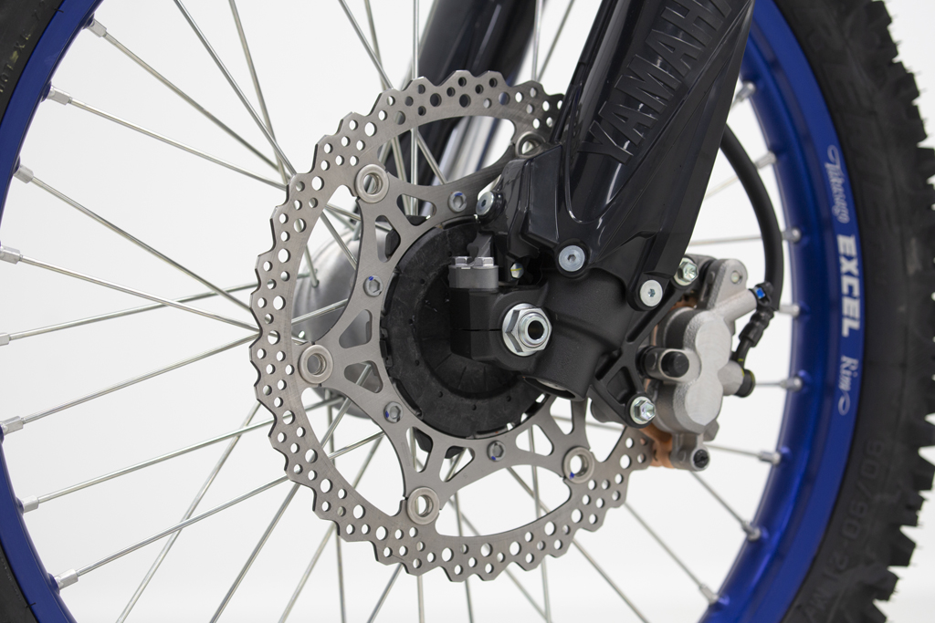
At the other end of the system, the caliper converts the hydraulic pressure back into mechanical force. When you apply the brake, the hydraulic pressure pushes the caliper pistons against the backs of the pads, advancing them about a tenth of a millimeter and pressing them against the disc. When you release the brake, the elasticity of the elastomer caliper piston seals causes the pistons to move back very slightly, allowing the rotor to spin without friction. When the pads wear enough to allow it, the caliper piston breaks its grip just enough to slide slightly through its seal, adopting a new position closer to the disc.
The actual force produced by the piston is equal to the line pressure multiplied by the area of the moving piston. In the case of a multi-piston design, the total force is equal to that of all cylinders combined.
Until relatively recently, brake calipers used on motorcycles were made of two-piece cast aluminum (which facilitates the boring of their pistons), with the two sections then bolted together. In the case of multi-piston calipers, an internal or external line was used to balance the pressures in the many cylinders. More recent calipers, known as “monobloc” calipers, are machined from a solid piece, forged for increased rigidity. In early versions, the piston bore was made by holes on one side, which were then closed with screw plugs. More recently, machining is carried out by means of a special device from inside the pad slot, so that no plugs are required.
Axial and radial
Here are two terms that are sometimes used when talking about brake components. In the context of the master cylinder, it refers to the mechanism by which the lever force is applied to the piston. In the case of an axial master cylinder, the brake lever presses against the master cylinder at an angle of approximately 90 degrees to the force exercised by the fingers; that is, the finger pressure axis is vertical while the master cylinder piston is mounted in a horizontal axis. In the radial version, the force exerted by the hand is in the same axis as that exerted on the piston. Once the exclusive domain of racing bikes, this design is becoming increasingly popular on production models due to its increased rigidity and precision.
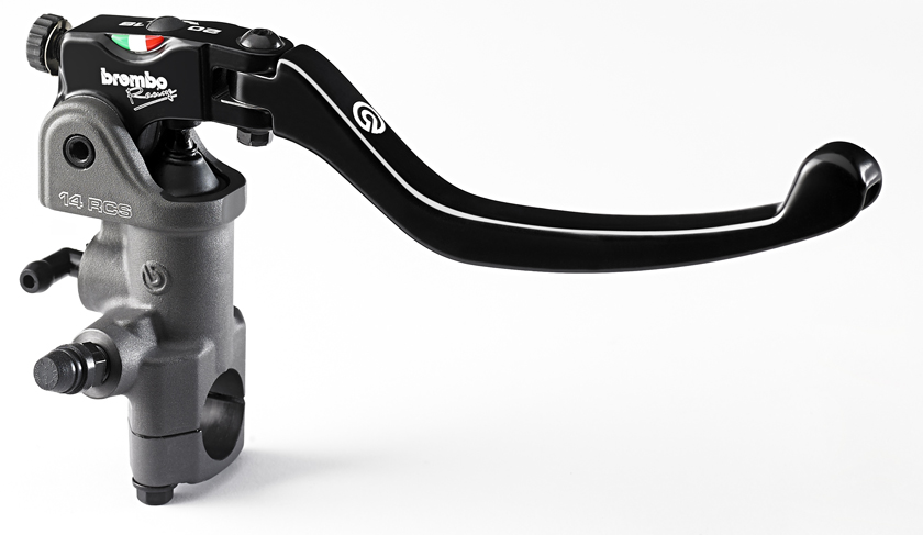
Moving on to calipers (especially those used at the front), the axial design is joined to the fork leg by bolts resting in an axis perpendicular to the front wheel, whereas the radial caliper uses bolts mounted parallel to the wheel axis. In practice, the radial mount is more rigid, allowing for better performance and lighter construction. As with the radial master cylinder, radial calipers have evolved on the racetrack and have now become popular on road models.
